


Abstract
Background: For the management of distal radius fractures, surgical decision-making depends on radiographic measurements of indicators including radial inclination (RI), ulnar variance (UV) and radial tilt (RT). Evaluation of the inter- and intrarater reliability of surgeons’ measurements of these criteria has been limited.
Methods: Twelve physicians were invited to participate in this study. Anonymously, they measured RI, UV and RT on 30 digitally stored radiographs of distal radius fractures on 3 occasions, each at least 1 week apart, using online measuring tools. After taking the third set of measurements, the participants were given a tutorial by the senior author (G.J.) on a single technique to measure all 3 indicators. The participants then took 3 more sets of measurements using only the technique they had been taught. Intraclass correlation coefficients (ICCs) were used to evaluate interrater reliability each week. Multiple logistic regression was used to calculate the effect of the tutorial, controlling for week of study along with reader (participant) and patient variance.
Results: The ICCs indicated that the participants’ measurement precision improved promptly after the tutorial, and this improvement was sustained through subsequent readings. The odds of an “accurate” measurement (within 2° of the senior author’s measurements for RI, 1 mm for UV and 4° for RT) was 1.7 times higher for RI, 2.7 times higher for UV and 2.3 times higher for RT after the tutorial; all of these results were statistically significant.
Conclusion: Surgeons ought to be familiar with a method to reproducibly measure the indicators used in the published guidelines for surgical intervention. The tutorial on a single standardized technique for online measurement of RI, UV and RT in distal radius fractures improved measurement precision.
Distal radius fractures (DRFs) are the most common adult fracture and their incidence is on the rise.1–4 Surgical fixation is becoming an increasingly common DRF treatment amid growing concerns about the poorer clinical outcomes, including residual deformity, associated with nonoperative management.4 Prevention of distal radius deformity is one of the key components of the decision-making process for management of these fractures.5,6
Anatomic deformity in DRFs is measured from radiographs in several ways, including radial height, radial inclination (RI), ulnar variance (UV), radial tilt (RT), articular step and gap, and metaphyseal comminution.7 Orthopedic surgeons have defined radiographic thresholds beyond which they would recommend surgery. For instance, the 2011 American Academy of Orthopaedic Surgeons’ guideline on the treatment of DRFs recommended, with moderate strength of conviction, operative fixation over cast treatment alone for fractures with postreduction radial shortening greater than 3 mm, dorsal tilt greater than 10° or intraarticular displacement or step-off greater than 2 mm.8 Boszotta and colleagues concluded that the same degree of shortening and dorsal tilt were clear indications for operative treatment.9 Guidelines adopted by Nana and colleagues for acceptable reduction were radial shortening less than 5 mm, RI greater than 15° and sagittal tilt (RT) on lateral projection between 15° dorsal tilt and 20° volar tilt.10 Dixon and colleagues noted that the 3 mm radial shortening threshold was a significant factor contributing to the risk of malunion.11
Despite the frequency with which DRFs occur and the central role that radiographic measurements play in surgical decision-making, there is no standardized method of measurement recommended for use by orthopedic surgeons. Furthermore, it is not known how reproducible, and indeed how accurate, the currently used methods for describing these radiographic values are. For example, there are multiple techniques for determining ulnar variance, including project-a-line,12 concentric circles,13 perpendiculars,14 the central reference point15 and lateral view.16 Parker and colleagues, however, found that although the latter 3 methods had clinically acceptable inter- and intraobserver reliability independently, the measurements taken with each method had considerable disagreement with the others.16 In light of this lack of standardization for measuring these important factors in DRF surgical decision-making, we designed this study to describe a single, simple, standardized technique to measure RI, UV and RT and to assess the inter- and intrarater reliability of physicians’ measurements of these 3 indicators before and after they viewed a tutorial on technique, the null hypothesis being that the tutorial would have no impact on measurement precision.
Methods
The technique to measure RI, UV and RT from DRF radiographs that the senior author (G.J.) has used consistently for the last decade was formally defined and explained in a 3-slide digital presentation, which was prepared for use in conjunction with a tutorial. The technique employs online angle and ruler measurement tools to evaluate digital images.
The senior author selected 30 standard zero-rotation (SZR) posteroanterior (PA) and lateral radiographs of DRFs in adult women who were at varying stages of healing, with the intention of creating a set of radiographs that were typical of clinical practice and that provided a broad range of levels of difficulty in terms of interpretation. The selected radiographs were from women treated by the senior author at the Royal University Hospital in Saskatoon, stored in the Saskatchewan Health Authority’s Picture Archiving and Communication System (PACS). In 19 of the 30 pairs of radiographs (PA and lateral; 60 radiographs in total) there was either a plaster of Paris or fibreglass cast in place. The remaining 11 cases did not have either cast material present. For 2 of the pairs of radiographs there was internal fixation, which in both cases was achieved using volar locking plates. The radiographs were deidentified, assigned aliases and uploaded into an electronic folder on the Royal University Hospital’s PACS, where they were accessible to all study participants. The hospital’s PACS has integrated calibrated online tools for measuring angles and distances.
To evaluate the precision of physicians’ measurements of these radiographic features, the 2 orthopedic specialists in the author group (an orthopedic resident in their fifth postgraduate year [S.F.] and an upper extremity orthopedic surgeon [G.J.]) recruited 10 additional physicians to participate in the study. In total, there were 4 orthopedic surgeons (2 trauma and 2 upper-extremity surgeons), 6 orthopedic trainees (in postgraduate years 1–5) and 2 musculoskeletal radiologists.
The participants viewed all 30 pairs of DRF radiographs. Using the online angle and ruler tools, they measured and recorded RI, UV and RT for each radiograph. The participants used their own methods to take the measurements. They repeated the measurements at no less than 1-week intervals on 2 additional occasions, recording their results on a scoring sheet each time. One week after the third reading, the senior author gave each participant a brief (approximately 5–10 min) one-on-one tutorial instructing the participant on a single measurement technique for the 3 indicators that he or she was to adopt for the subsequent 3 readings. At the same time, a 3-slide digital presentation (Fig. 1, Fig. 2 and Fig. 3) explaining the same technique of measurement was forwarded to each participant electronically. The senior author then asked the participant to promptly resume the weekly measurements, taking them on 3 additional occasions, again at no less than 1-week intervals. The same 3-slide digital presentation was forwarded to each participant with a scoring sheet each week. For comparison, the senior author also measured and recorded RI, UV and RT for each radiograph on 6 occasions at weekly intervals.
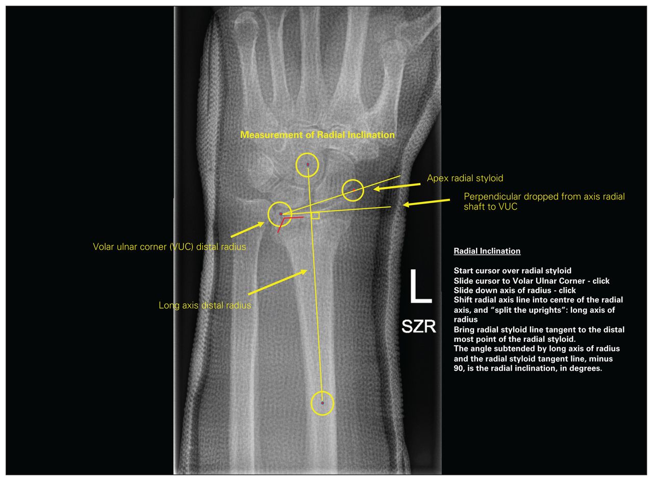
First slide of a 3-slide PowerPoint presentation on how to take radiographic measurements to assess anatomic deformity in distal radius fractures. This slide indicates how to determine radial inclination. SZR = standard zero rotation; VUC = volar ulnar corner.

Second slide of a 3-slide PowerPoint presentation on how to take radiographic measurements to assess anatomic deformity in distal radius fractures. This slide indicates how to determine ulnar variance. SZR = standard zero rotation; VUC = volar ulnar corner.

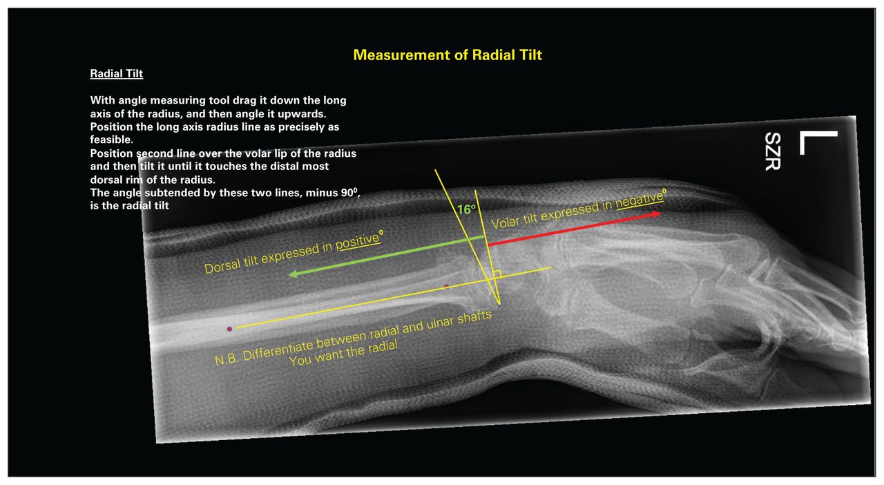
Third slide of a 3-slide PowerPoint presentation on how to take radiographic measurements to assess anatomic deformity in distal radius fractures. This slide indicates how to determine radial tilt. SZR = standard zero rotation.
Measurement technique
Central to the measurement technique is the “pivot point” at the volar ulnar corner of the distal radius on the PA radiograph. The first limb of the online angle-measuring tool is drawn along the distinct, sourcil-like, volar rim of the distal radius in a radial to ulnar direction; the point where this intersects the first of the 2 vertical lines that outline the volar and dorsal radial brims of the sigmoid notch defines the radial volar ulnar corner or pivot point (Fig. 4). From this point the second limb is drawn in a proximal direction, roughly parallel to the axis of the radial shaft. This second limb is then translated radially to overlie the centre of the distal radial shaft, and it is adjusted to bisect the metaphysis of the radius at the level of the transverse component of the fracture complex, to “split the uprights” of the radius as precisely as possible. This line represents the longitudinal axis of the radius. Pivoting on the radial volar ulnar corner or pivot point, the original first limb of the angle tool is rotated to be tangent to the distal tip of the radial styloid. The angle displayed, less 90°, indicates the degree of RI (Fig. 1). This same first limb is rotated further about the pivot point to achieve a right angle to the longitudinal axis of the radius, and this perpendicular line is extended ulnarly. Another perpendicular is dropped from this line to the most distal aspect of the head of the ulna; UV is defined as this distance (in mm), and it is assigned a negative or positive value if the head is proximal or distal to this perpendicular, respectively (Fig. 2).

Radiograph illustrating the “pivot point.” The point where the volar rim of the distal radius intersects the volar brim of the sigmoid notch defines the radial volar ulnar corner or pivot point.
On the lateral distal radial radiograph, the angle subtended by a line from the volar to dorsal rims of the distal radius and another line perpendicular to the longitudinal axis of the distal radius defines RT; it is assigned a negative value if directed volarly and a positive value if directed dorsally (Fig. 3).
Measuring reader precision
Intraclass correlation coefficients (ICCs) were used to evaluate interrater reliability each week, for each measurement. 17 An objective measure of precision was determined as follows: for the “gold standard” (the senior author), the range of measurements over the 6 weeks was calculated, and then the 75th quartile of those numbers was used as a precision threshold. Although no gold standard for measurement of these indicators exists, the senior author has made more than 10 000 measurements of each of these indicators in his DRF clinical practice with the online measurement tools used in this study; as such, for this study, this experience was presumed to qualify him as an expert and the de facto gold standard.
Comparisons of the measurements taken by the participants with those of the gold standard were performed weekly using simple t tests. Using the 75% quartile as the standard, we classified every other reading in the study as accurate if it was within the standard value of the senior author’s measurement for that week. Using these values, we used multiple logistic regression to calculate the effect of the intervention (tutorial), controlling for week of study along with reader and patient variance.
Results
The time interval from submission of the first reading to the last was 92 days. All participants completed 100% of their readings and recordings, for a total of 6480 measurements.
The senior author intended the radiographs to represent a broad range of difficulty to interpret: the greater the standard deviation for each measure, the more challenging the interpretation, and the lower the standard deviation for each measure, the easier the interpretation. The radiographs were ranked according to the consistency of measurement (Table 1).
Overall standard deviations for each radiographic measure
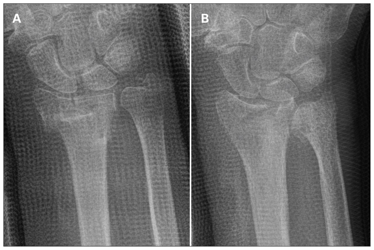
For the measurements made by the senior author, there was a 35° range in RI values (from 6° to 41°), an 11.9 mm range in UV values (from −1.2 mm to 10.7 mm) and a 59° range in RT values (from 25° of volar tilt to 34° of dorsal tilt). Examples of the radiographs with the lowest and highest variation for the measurements of RI, UV and RT are presented in Figure 5, Figure 6 and Figure 7, respectively.

Radiographs associated with the lowest and highest standard deviations for measurements of radial inclination. (A) Radiograph 27 was associated with the lowest variation (i.e., it was the easiest to interpret). (B) Radiograph 1 was associated with the highest variation (i.e., it was the most challenging to interpret).
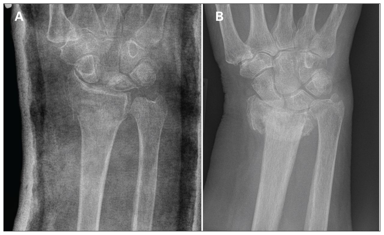
Radiographs associated with the lowest and highest standard deviations for measurements of ulnar variance. (A) Radiograph 26 was associated with the lowest variation (i.e., it was the easiest to interpret). (B) Radiograph 2 was associated with the highest variance (i.e., it was the most challenging to interpret).

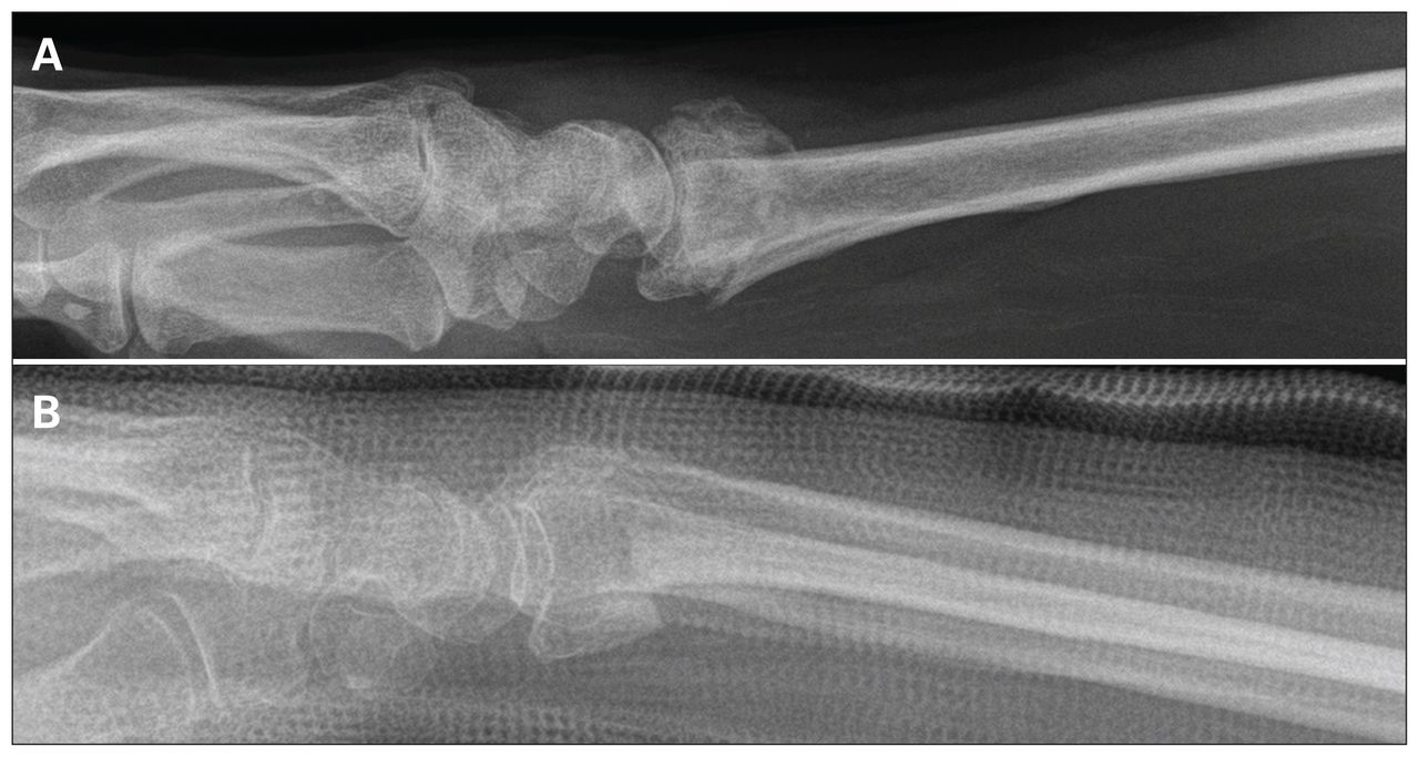
Radiographs associated with the lowest and highest standard deviations for measurements of radial tilt. (A) Radiograph 20 was associated with the lowest variation (i.e., it was the easiest to interpret). (B) Radiograph 8 was associated with the highest variation (i.e., it was the most challenging to interpret).
The ICCs for RT, UV and RI indicated that measurements became more consistent after the participants adopted the standardized measurement technique (Fig. 8).
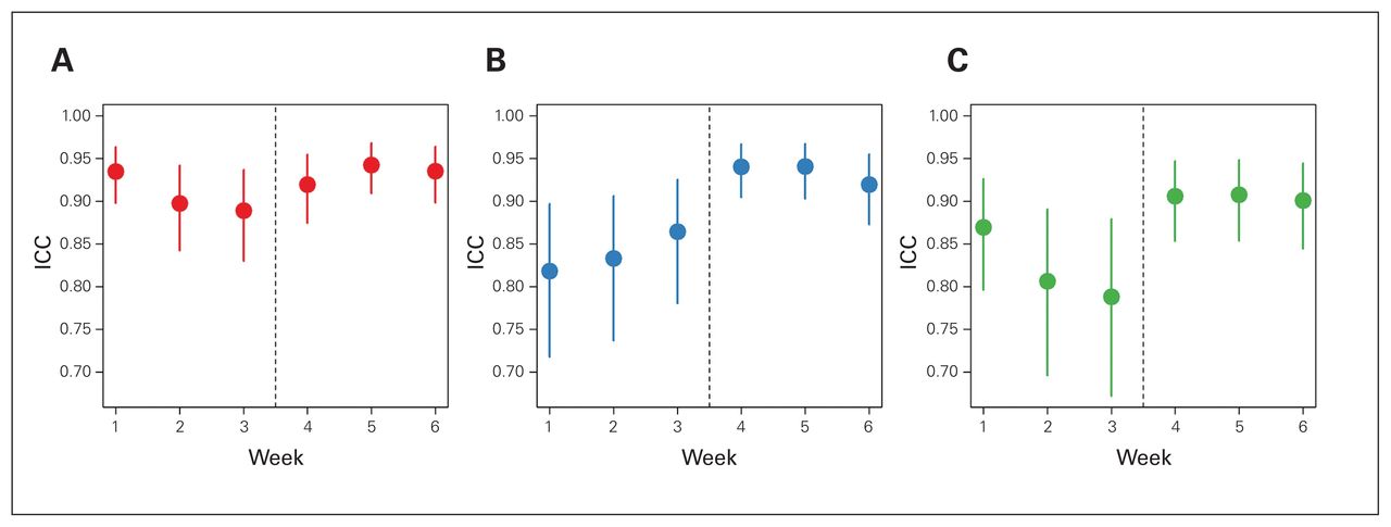
Intraclass correlation coefficients and their confidence intervals for each of the 3 measures: (A) radial tilt, (B) ulnar variance and (C) radial inclination. The intraclass correlation coefficients for radial tilt, ulnar variance and radial inclination reflected improved consistency of measurement after the adoption of the standardized measurement technique. ICC = intraclass correlation coefficient.
Table 2 presents the quartiles for the range of values for the gold standard. For example, among all of the patients for whom the senior author measured RI values over the 6 readings, 50% of those patients had a 1° range between the lowest and highest value and 75% had a 2° range.
Quartiles for variability in the measurements taken by the senior author (G.J.) over the 6-week study period
Table 3 presents the precision of the measurements of RT, UV and RI over the 6-week study period, along with the results of the modelling. There was statistically significant improvement in the precision of all 3 types of measurements after the intervention, with odds ratios ranging from 1.7 to 2.7. Patient variance reflected the degree of difficulty that readers encountered in measuring RE, UV and RT.
Precision of measurements and effect of training*
Discussion
Accurate measurement of angles and distances facilitates evaluation of postreduction DRF radiographs and comparison of serial recordings in the context of nonoperative care, and it informs surgical decision-making. The ideal technique to measure these radiographic features ought to be quick to perform, easy to reproduce, and valid. In this study, an intervention to teach physicians a single, simple-to-perform technique to measure UV, RI and RT from digitally stored DRF radiographs using online tools was associated with significant improvement in the precision of these measurements.
Several techniques to measure RI and UV for DRFs have been reported in the literature. They are differentiated by their definition of the location of an ulnar-sided radial reference point. It is critical that this reference point be consistent in DRF parlance to ensure that the measurements are meaningful; at present, different RI references, for example, beget different RI measurements.
Medoff and colleagues described a central reference point (CRP), found by bisecting a line drawn between the dorsal and volar corners of the sigmoid notch.15,18,19 From the central reference point, RI and UV are measured similarly to the method described above. To determine the central reference point, however, both volar and dorsal corners of the sigmoid notch must be determined. Whereas volar corner disruption is typically the exception in DRFs, dorsal disruption is often the rule. It may be difficult to consistently define the central reference point in DRF evaluation.
Blakeney and colleagues measured RI as the angle subtended by a line perpendicular to the longitudinal axis of the radius and a line joining the distal tip of the radial styloid and the distal sigmoid notch.20 Again, the anticipated dorsal comminution of DRFs risks complicating and hampering accurate RI measurement.
In contrast, it is generally easy to pinpoint the volar ulnar corner of the distal radius, the pivot point for measurement in this study. In the atypical situation where the volar ulnar corner is difficult to determine, the surgeon should suspect volar ulnar radial disruption and consider using computed tomography to better define the anatomic pathology.
In this study, all radiographs were assessed using online digital tools. Grainger and colleagues found that use of such tools not only substantially decreased the time that it took to measure radial angle (RI), radial shift, radial length, palmar tilt and dorsal shift (from 12 to 4 min) but also improved intra- and interrater variation for all measures except posterior tilt.21 Bozentka and colleagues compared measurements from plain and digital radiographs using a hand-held goniometer and available software, respectively. They demonstrated that measurement of the digital images improved interobserver reliability for palmar tilt and radial height and intraobserver reliability for radial height.22 Robertson and colleagues recommended regular use of the PACS measuring tool over visual estimation.23 In this study, only digitally stored PACS radiographs were used, along with PACS’ integrated measurement software.
Even the senior author, whose clinical practice is principally focused on DRFs, could not reproduce exactly the measurements of RI, UV and RT in this 30-radiograph sample; the variations in the reading results confirmed that the images selected for this study represent a broad range of difficulty in terms of interpretation. Examples of confounding elements include the presence of an overlying cast and rounding of the radial styloid and comminution of the volar ulnar corner of the distal radius; the latter would have an impact on the measurement of RI and UV, given that the ulnar reference pivot point cannot be reliably defined.
The wide range of values for the senior author’s measurements of RI, UV and RT ensured that ICCs could not be artificially high, a phenomenon more likely to be encountered when ranges are small.
Given this variation, the 75% quartile range was selected as the precision threshold, specifically 2° for RI, 1.8 mm for UV and 4° for RT. Rajabi and colleagues recorded the precision (standard error) of RT measurement as 3.5° for right angle lateral projection,24 similar to the 75% quartile value of 4° used in the present study.
Only SZR PA and lateral radiographs were used in this study. We assumed no forearm malrotation, which has been demonstrated to influence RI, UV and RT.25–27 For example, Pennock and colleagues noted that as little as 10° of forearm pronation decreased the apparent RI, radial height and RT by 2.8°, 1.6 mm and 4.4°, respectively.28
Before the intervention (the tutorial), the ICCs did not trend upward, suggesting that repetition itself did not lead to improvement in reading precision. Reading precision did improve, however, after the tutorial. The definition of the pivot point, which is key to the interpretation of the PA radiographs, probably explains the improvements seen in this study. Although the tutorial did not offer a novel method of measuring RT from lateral radiographs, reading precision still improved. The overall results suggest that practitioners who collaborate in the management of DRFs should consider adopting a common technique of measurement.
Kreder and colleagues calculated the ICC for RI, UV and RT as 0.39, 0.85 and 0.71 in established distal radial malunions without superimposed casting material, demonstrating the difficulties encountered in measuring these radiographic features.29 Jafari and colleagues reported the ICCs (interobserver) for assessment of radial length, RI and RT to be 0.672, 0.649 and 0.631, respectively; the ICCs (intraobserver) for radial length and RT were 0.606 and 0.605, respectively, and 0.582 for RI.30 Stirling and colleagues reported interobserver correlation greater than 0.8 for 3 of the 4 measurements by 2 assessors. Ten percent of the radiographs (n = 37) were reassessed 4 weeks later and intraobserver agreement was greater than 0.8.31 The range of values was unclear, as was the assessment of the difficulty in reading the radiographs. In this study the ICC values, a measure of agreement, were high, strongly suggesting that the pivot-point technique was reproducible among many readers.
This study has several strengths. The measurement technique is easy to perform and teach, it improves the precision of measurements taken by a variety of physicians and surgeons with varying levels of experience, it is not confounded by dorsal radial comminution and it is relevant to the current practice of online assessment of radiographic anatomy using digitally stored DRF images. The radiographs were from real-life scenarios and presented a wide range of levels of difficulty in terms of interpretation, and they exposed the difficulties that even experts encounter in interpreting DRF radiographs. Even for proficient readers who have had considerable practice, it can be difficult to take precisely reproducible readings of anatomic landmarks obscured by fracture comminution, for example. The 100% completion rate in this study gave credence to the statistical evaluation; it was not necessary to use statistical techniques to account for missing values.
None of the orthopedic surgeons and radiologists who participated in the study (other than the senior author) had been schooled on the online digital pivotpoint technique before the study. The more senior orthopedic residents may have been aware of the technique, but they were not familiar with its specifics. Despite this potential weakness, improvement in precision was consistent following the tutorial.
Limitations
A limitation of the study may be that it did not compare the measured values with those derived using other techniques. The distal radial volar ulnar corner pivot point, being more proximal to both the reference point described by Medoff and colleagues and the reference point described by Blakeney and colleagues, in comparison, will overestimate measurements of both RI and UV. Interestingly, however, the literature does not specifically define a validated method of measurement of the threshold values identified for DRF surgical intervention, rendering the need for comparison moot.
Conclusion
Adoption of an easily taught, simply performed, online, single measurement technique for RI, UV and RT had a prompt and sustained impact, significantly improving physicians’ precision in measuring these important indicators in surgical decision-making in DRF management.
Acknowledgements
The authors thank the participants in the study, on whose professionalism they were able to rely: Drs. James Ardell, William Dust, Tanner Gurney-Dunlop, Heather Hansen, David Leswick, Haron Obaid, Elliott Pally, Alexander Perreault, David Sauder and Laura Sims. They also thank Mr. Peter Barboluk whose assistance made it possible to display the radiographs on PACS.
Footnotes
Competing interests: None declared.
Contributors: All authors designed the study. G. Johnston and S. Fox acquired the data, which all authors analyzed. All authors wrote and critically reviewed the article, and all authors gave final approval of the article to be published.
- Accepted September 27, 2019.
References
In this issue

Article tools


Related Articles
Cited By...
- No citing articles found.